与Juniper SRX建立ipsec vpn
下面案例中讲述如何与SRX建立IPsec vpn Junos版本是11.0
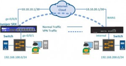
拓扑如下
阶段1的参数
|
VPN Parameters |
Juniper SRX |
防火墙 |
||
|
Phase-I (IKE) |
Authentication Method |
Preshared key |
Preshared key |
|
|
Authentication- Algorithm |
Sha1 |
Sha1 |
||
|
Encryption- Algorithm |
3Des-cbc |
3Des-cbc |
||
|
dh-group |
5 |
5 |
||
|
Lifetime (sec) |
28800 |
28800 |
||
|
Mode |
Main |
Main |
||
|
Remote gateway Address |
10.10.20.2 |
10.10.10.2 |
||
|
Nat-keepalive |
10 |
10 |
||
|
Phase-II (IPSEC) |
Protocol |
Esp |
Esp |
|
|
Authentication- Algorithm |
sha1-96 |
sha1-96 |
||
|
Encryption- Algorithm |
3Des-cbc |
3Des-cbc |
||
|
PFS keys Groups |
5 |
5 |
||
|
Lifetime (sec) |
86400 |
86400 |
||
|
Proxy-identity |
local |
192.168.100.0/24 |
192.168.200.0/24 |
|
|
remote |
192.168.200.0/24 |
192.168.100.0/24 |
||
|
Service |
Any |
Any |
||
|
Locally Significant |
Outgoing interface |
ge-0/0/0 |
Wan1 |
|
|
Tunnel interface |
st0.1 |
|
||
先配置SRX端的
|
user@SRX#set interfaces ge-0/0/0 unit 0 description ” WAN INTERFACE “ user@SRX#set interfaces ge-0/0/0 unit 0 family inet address 10.10.10.2/30 |
Defineure the LAN side interfaces and assigning the IP address
|
user@SRX#set interfaces ge-0/0/1 unit 0 description ” LAN INTERFACE “ user@SRX#set interfaces ge-0/0/1 unit 0 family inet address 192.168.100.1/24 |
Defineure the VPN tunnel interfaces
|
user@SRX#set interfaces st0 unit 1 description ” VPN SECURE TUNNEL “ user@SRX#set interfaces st0 unit 1 family inet |
Defineure default route and route for tunnel traffic
For route of tunnel traffic, next-hop would be normally the gateway ip address of peer device but here st0.1 has been specified as there is not defined the IP address in tunnel interface of peer Device.
|
user@SRX#set routing-options static route 0.0.0.0/0 next-hop 10.10.10.1 user@SRX#set routing-options static route 192.168.200.0/24 next-hop st0.1 |
Defineure security zones and assign interfaces to the zone and adding host-inbound system services in these zones
To separate the security policies for non-VPN and VPN traffic, the secure tunnel is assigned in different zone named VPN than the WAN and LAN zone.IKEmust be defined as host-inbound system services in internet facing zone (WAN) to establish theIKEnegotiations between VPN peer devices.
|
user@SRX#set security zones security-zone WAN host-inbound-traffic system-services ike user@SRX#set security zones security-zone WAN interfaces ge-0/0/0.0 user@SRX#set security zones security-zone LAN host-inbound-traffic system-services all user@SRX#set security zones security-zone LAN interfaces ge-0/0/1.0 user@SRX#set security zones security-zone VPN interfaces st0.1 |
Defineure Phase-I IKE proposal and Policy for main mode as listed above in Table
Here I have defined the VPN parameters manually instead of using the default for Phase-I.
|
user@SRX#set security ike proposal IKE-PROPOSAL authentication-method pre-shared-keys user@SRX#set security ike proposal IKE-PROPOSAL dh-group group5 user@SRX#set security ike proposal IKE-PROPOSAL authentication-algorithm sha1 user@SRX#set security ike proposal IKE-PROPOSAL encryption-algorithm 3des-cbc user@SRX#set security ike proposal IKE-PROPOSAL lifetime-seconds 28800 user@SRX#set security ike policy IKE-POLICY mode main user@SRX#set security ike policy IKE-POLICY proposals IKE-PROPOSAL user@SRX#set security ike policy IKE-POLICY pre-shared-key ascii-text |
Defineure the VPN gateway (Phase-I) with policy, peer address and outgoing interface
To identify the remoteIKEpeer, I have used IP address of peer device and outgoing interface ge-0/0/0 of SRX device.
|
user@SRX#set security ike gateway VPN-GATEWAY ike-policy IKE-POLICY user@SRX#set security ike gateway VPN-GATEWAY address 10.10.20.2 user@SRX#set security ike gateway VPN-GATEWAY dead-peer-detection interval 10 user@SRX#set security ike gateway VPN-GATEWAY dead-peer-detection threshold 1 user@SRX#set security ike gateway VPN-GATEWAY nat-keepalive 10 user@SRX#set security ike gateway VPN-GATEWAY external-interface ge-0/0/0.0 |
Defineure Phase-II Proposal and Policy as listed in above Table
Here I have defined the VPN parameters manually instead of using the default for Phase-II.
|
user@SRX#set security ipsec proposal IPSEC-PROPOSAL protocol esp user@SRX#set security ipsec proposal IPSEC-PROPOSAL authentication-algorithm hmac-sha1-96 user@SRX#set security ipsec proposal IPSEC-PROPOSAL encryption-algorithm 3des-cbc user@SRX#set security ipsec proposal IPSEC-PROPOSAL lifetime-seconds 86400 user@SRX#set security ipsec policy IPSEC-POLICY perfect-forward-secrecy keys group5 user@SRX#set security ipsec policy IPSEC-POLICY proposals IPSEC-PROPOSAL |
Defineure IPSEC VPN (Phase-II) with IKE gateway, IPSEC policy and Binding the Secure Tunnel st0.1 interface
|
user@SRX#set security ipsec vpn IPSEC-VPN bind-interface st0.1 user@SRX#set security ipsec vpn IPSEC-VPN ike gateway VPN-GATEWAY user@SRX#set security ipsec vpn IPSEC-VPN ike proxy-identity local 192.168.100.0/24 user@SRX#set security ipsec vpn IPSEC-VPN ike proxy-identity remote 192.168.200.0/24 user@SRX#set security ipsec vpn IPSEC-VPN ike proxy-identity service any user@SRX#set security ipsec vpn IPSEC-VPN ike ipsec-policy IPSEC-POLICY user@SRX#set security ipsec vpn IPSEC-VPN establish-tunnels immediately |
Defineure the security policy for internet Traffic from LAN to WAN zone
|
user@SRX#set security policies from-zone LAN to-zone WAN policy LAN_WAN match source-address any user@SRX#set security policies from-zone LAN to-zone WAN policy LAN_WAN match destination-address any user@SRX#set security policies from-zone LAN to-zone WAN policy LAN_WAN match application any user@SRX#set security policies from-zone LAN to-zone WAN policy LAN_WAN then permit |
Defineure the security NAT for internet Traffic from LAN to WAN zone
It is important to defineure NAT for passing internet traffic from LAN to WAN zone. LAN zone IP address will be translated to the egress interface IP of SRX as source IP when it goes to internet.
|
user@SRX#set security nat source rule-set LAN-TO_WAN from zone LAN user@SRX#set security nat source rule-set LAN-TO_WAN to zone WAN user@SRX#set security nat source rule-set LAN-TO_WAN rule SOURCE-NAT match source-address 0.0.0.0/0 user@SRX#set security nat source rule-set LAN-TO_WAN rule SOURCE-NAT match destination-address 0.0.0.0/0 user@SRX#set security nat source rule-set LAN-TO_WAN rule SOURCE-NAT then source-nat interface |
Defineure bi-directional security policy for tunnel traffic from and to LAN to VPN zone
Here bi-directional policies are defineured to pass the VPN traffic from and to LAN to VPN zone.
|
user@SRX#set security policies from-zone LAN to-zone VPN policy LAN_VPN match source-address any user@SRX#set security policies from-zone LAN to-zone VPN policy LAN_VPN match destination-address any user@SRX#set security policies from-zone LAN to-zone VPN policy LAN_VPN match application any user@SRX#set security policies from-zone LAN to-zone VPN policy LAN_VPN then permit user@SRX#set security policies from-zone VPN to-zone LAN policy VPN_LAN match source-address any user@SRX#set security policies from-zone VPN to-zone LAN policy VPN_LAN match destination-address any user@SRX#set security policies from-zone VPN to-zone LAN policy VPN_LAN match application any user@SRX#set security policies from-zone VPN to-zone LAN policy VPN_LAN then permit |
Defineure tcp-mss to eliminate fragmentation of TCP traffic across tunnel
The tcp-mss for IPSec traffic is defined to eliminate the possibility of fragmented TCP traffic. It limits the maximum size of a TCP Segment
user@SRX#set security flow tcp-mss ipsec-vpn mss 1350
Following command verifies the vpn tunnel and status.
-
user@SRX>show security ike security-associations
-
user@ SRX >show security ipsec security-associations
配置我方的防火墙
命令行下配置接口的设置
|
防火墙 # define system interface 防火墙 (interface) # edit wan1 防火墙 (wan1) # set ip 10.10.20.2 255.255.255.252 防火墙 (wan1) # set alias “WAN_INTERFACE” 防火墙 (wan1) # set allowaccess ping https ssh telnet 防火墙 (wan1) # end |
图形界面的设置

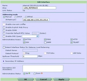
配置内网的IP地址
|
防火墙 # define system interface 防火墙 (interface) # edit internal 防火墙 (internal) # set ip 192.168.200.1 255.255.255.0 防火墙 (internal) # set alias “LAN_INTERFACE” 防火墙 (internal) # set allowaccess ping https http ssh telnet 防火墙 (internal) # end |
图形界面下的配置
.
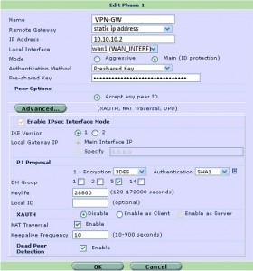
命令行下阶段1的配置
|
防火墙 # define vpn ipsec phase1-interface 防火墙 (phase1-interface) # edit VPN-GW 防火墙 (VPN-GW) # set mode main 防火墙 (VPN-GW) # set interface “wan1” 防火墙 (VPN-GW) # set proposal 3des-sha1 防火墙 (VPN-GW) # set dhgrp 5 防火墙 (VPN-GW) # set dpd enable 防火墙 (VPN-GW) # set keylife seconds 28800 防火墙 (VPN-GW) # set keepalive 10 防火墙 (VPN-GW) # set nattraversal enable 防火墙 (VPN-GW) # set remote-gw 10.10.10.2 防火墙 (VPN-GW) # set psksecret 防火墙 (VPN-GW) # end |
图形界面下的设置:
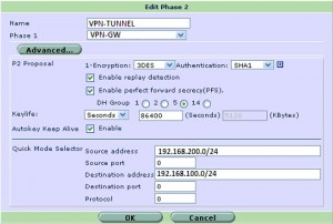
阶段2的命令行设置
|
防火墙 # define vpn ipsec phase2-interface 防火墙 (phase2-interface) # edit VPN-TUNNEL 防火墙 (VPN-TUNNEL ) # set phase1name “VPN-GW” 防火墙 (VPN-TUNNEL ) # set proposal 3des-sha1 防火墙 (VPN-TUNNEL ) # set reply enable 防火墙 (VPN-TUNNEL ) # set pfs enable 防火墙 (VPN-TUNNEL ) # set dhgrp 5 防火墙 (VPN-TUNNEL ) # set keylifeseconds 86400 防火墙 (VPN-TUNNEL ) # set keepalive enable 防火墙 (VPN-TUNNEL ) # set src-subnet 192.168.200.0 255.255.255.0 防火墙 (VPN-TUNNEL ) # set dst-subnet 192.168.100.0 255.255.255.0 防火墙 (VPN-TUNNEL ) # end |
图形界面的设置
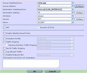
定义从外到内防火墙的策略.
命令行下设置:
|
防火墙 # define firewall policy 防火墙 (policy) # edit 1 防火墙 (1) # set srcintf VPN-GW 防火墙 (1) # set dstintf internal 防火墙 (1) # set srcaddr “all” 防火墙 (1) # set dstaddr “all” 防火墙 (1) # set action accept 防火墙 (1) # set schedule “always” 防火墙 (1) # set service “ANY” 防火墙 (1) # end |
图形界面设置
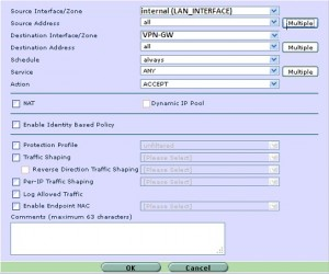
定义从内到外的策略
|
防火墙 # define firewall policy 防火墙 (policy) # edit 1 防火墙 (1) # set srcintf internal 防火墙 (1) # set dstintf VPN-GW 防火墙 (1) # set srcaddr “all” 防火墙 (1) # set dstaddr “all” 防火墙 (1) # set action accept 防火墙 (1) # set schedule “always” 防火墙 (1) # set service “ANY” 防火墙 (1) # end |
图形界面设置
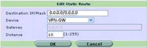
配置路由,设置目标地址流量通过vpn进行转发。在本例中所有流量都转入通道,如果只转相应网段的流量,那么配置相应路由即可。
|
防火墙 # define router static 防火墙 (static) # edit 1 防火墙 (1) # set device “VPN-GW” 防火墙 (1) # end |
图形界面设置