旁路式防火墙配置案例
KFW防火墙旁路式部署配置案例
如果原有网络拓扑已经完善,防火墙加入时不想对原网络进行太大修改,或者是上行出口较多时,可以将防火墙进行旁路时部署,保证通信正常和安全。
1.网络部署方案一
1.1.网络拓扑
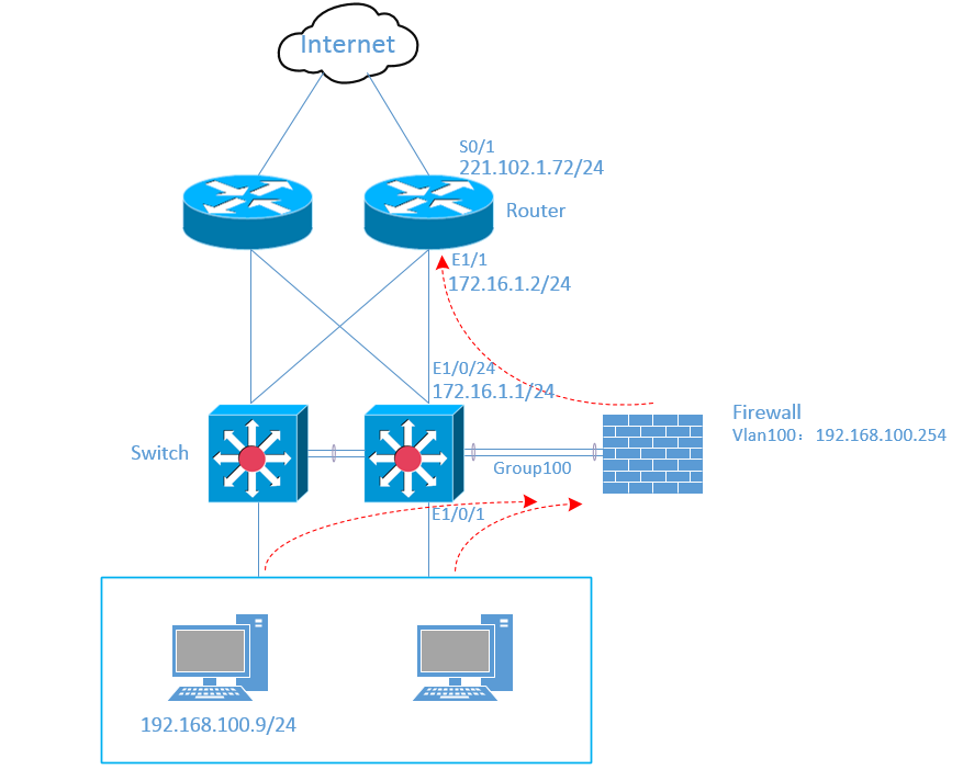
如图所示,防火墙旁挂于核心交换机,内网访问数据流先经过核心交换到防火墙,防火墙过滤后再由核心交换转发给路由器出去,回来时数据流反向经过防火墙过滤。
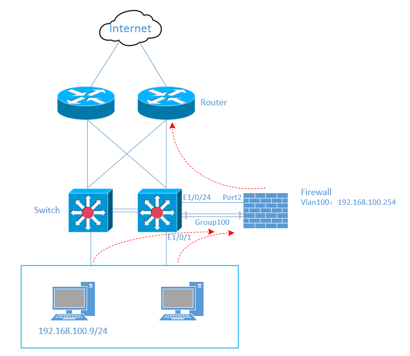
PC192.168.100.9接于核心交换机E1/0/1端口,核心交换机与防火墙之间建立以太网通道PortGroup100;数据流经防火墙后出口为Port2,连接核心交换机E1/0/24端口,此段链路启用三层功能。
1.2.设备配置
本案例中只介绍与案例相关的配置,其他配置默认已配好。
1.2.1.交换机配置
-
新建vlan100,并将端口E1/0/1加入vlan100。
#config terminal
(config)#vlan 100
(config-vlan100)#exit
(config)#interface e1/0/1
(config-if-ethernet1/0/1)#switchport mode access
(config-if-ethernet1/0/1)#switchport acceess vlan100
(config-if-ethernet1/0/1)#exit
-
新建以太网通道port-channel 100,并将端口E1/0/23、E1/0/24加入port-channel 100,分别接入防火墙的Port6、Port7端口。
(config)#port-group 100
(config)#interface port-channel 100
(config-if-port-channel100)#switchport mode trunk
(config-if-port-channel100)#exit
(config)#interface e1/0/23
(config-if-ethernet1/0/23)#port-group 100 mode active
(config-if-ethernet1/0/23)#exit
(config)#interface e1/0/24
(config-if-ethernet1/0/24)#port-group 100 mode active
(config-if-ethernet1/0/24)#exit
1.2.2.防火墙配置
-
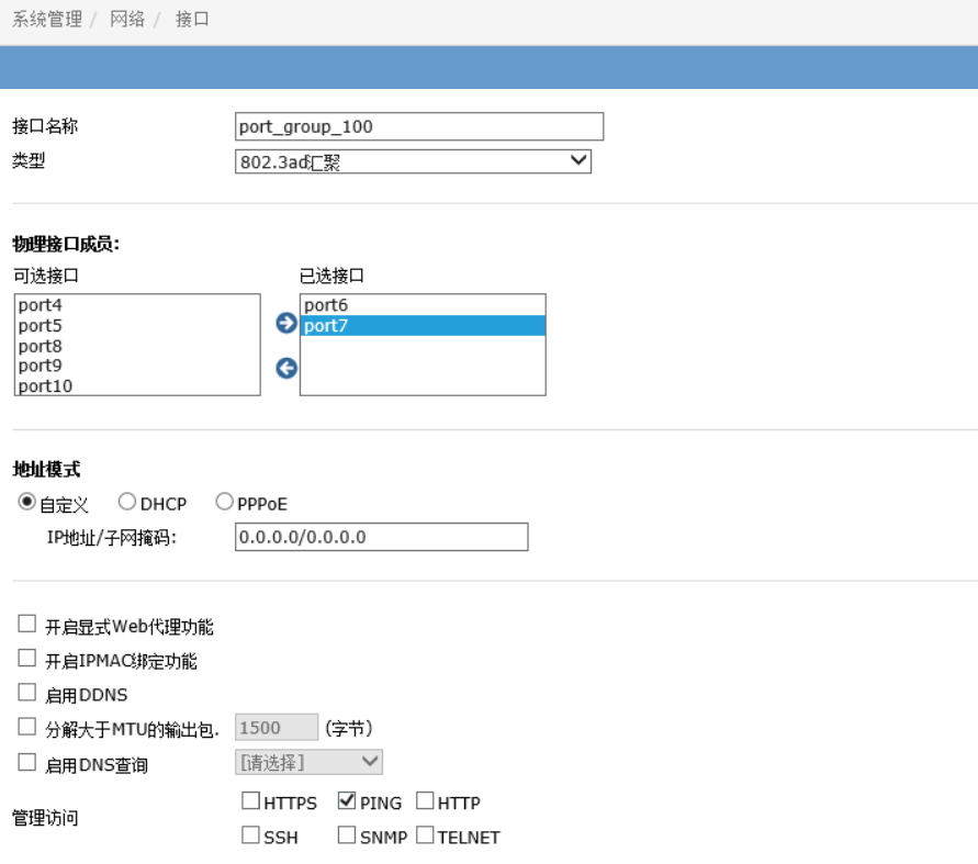
进入“系统管理>网络>接口”页面,创建聚合端口port_group_100,并将port6、port7加入该聚合端口。
-
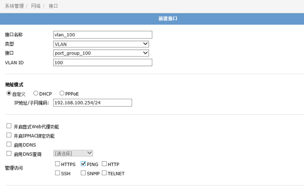
在聚合端口port_group_100下创建vlan100,并配置网关192.168.100.254/24。
-
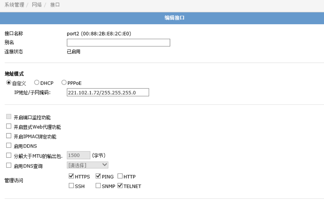
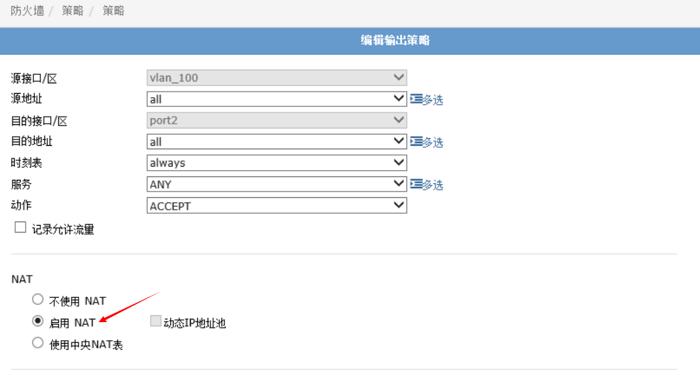
配置防火墙port2端口为网络出口。
-
配置安全策略,允许vlan100的流量出去,并在端口进行NAT转换。
-
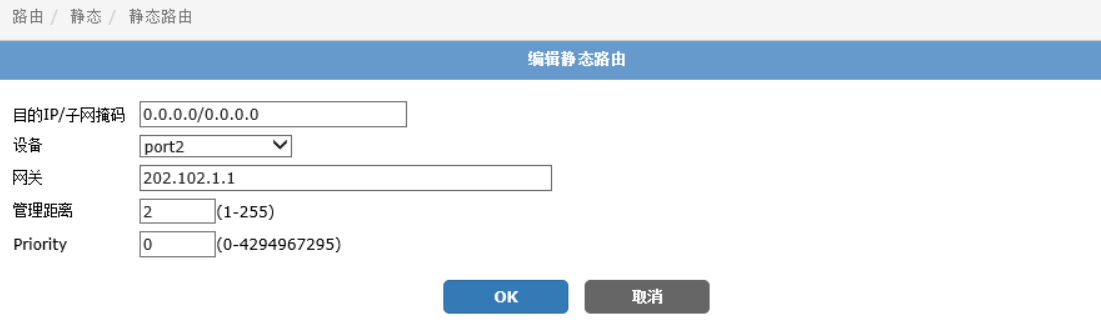
配置默认路由,指定出口下一跳。
-
在PC终端配置IP地址192.168.100.9/24,经测试可正常访问互联网。
2.网络部署方案二
2.1.网络拓扑
如图所示,防火墙旁挂于核心交换机,内网数据流通过以太网通道Group100与核心交换机进行交互,返回时数据流相反走向。
2.2.设备配置
本案例中只介绍与案例相关的配置,其他配置默认已配好。
2.2.1.交换机配置
-
新建vlan100,并将端口E1/0/1加入vlan100。
#config terminal
(config)#vlan 100
(config-vlan100)#exit
(config)#interface e1/0/1
(config-if-ethernet1/0/1)#switchport mode access
(config-if-ethernet1/0/1)#switchport acceess vlan100
(config-if-ethernet1/0/1)#exit
-
新建以太网通道port-channel 100,并将端口E1/0/23、E1/0/24加入port-channel 100,分别接入防火墙的Port6、Port7端口。
(config)#port-group 100
(config)#interface port-channel 100
(config-if-port-channel100)#switchport mode trunk
(config-if-port-channel100)#exit
(config)#interface e1/0/23
(config-if-ethernet1/0/23)#port-group 100 mode active
(config-if-ethernet1/0/23)#exit
(config)#interface e1/0/24
(config-if-ethernet1/0/24)#port-group 100 mode active
(config-if-ethernet1/0/24)#exit
-
在端口E1/0/24配置与路由器互连端口IP,请确认交换机开启三次路由功能。
(config)#intface e1/0/24
(config-if-ethernet1/0/24)#ip address 172.16.1.2 255.255.255.0
(config-if-ethernet1/0/24)#no shutdown
(config-if-ethernet1/0/24)#exit
2.2.2.路由器配置
在出口防火墙上配置对应端口IP和NAT功能,具体配置省略。
2.2.3.防火墙配置
-
进入“系统管理>网络>接口”页面,创建聚合端口port_group_100,并将port6、port7加入该聚合端口。

-
在聚合端口port_group_100下创建vlan100,并配置网关192.168.100.254/24。

-
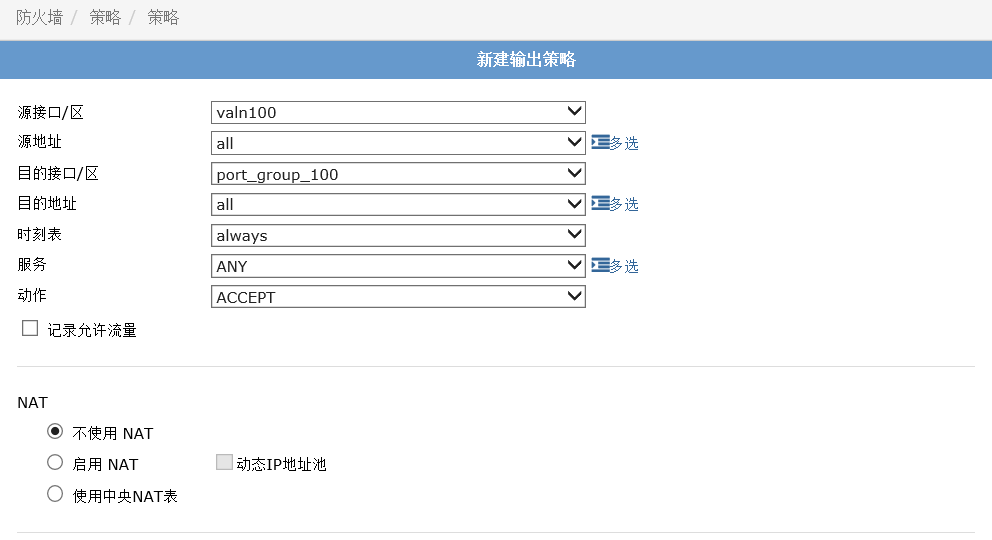
配置安全策略,允许vlan100的流量出去。
-
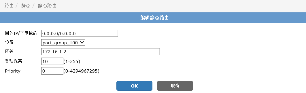
配置默认路由,指定出口和下一跳。
-
在PC终端配置IP地址192.168.100.9/24,经测试可正常访问互联网。